2.625″ I.D., 3.628″ O.D., 0.375″ wide
Also fits the follow gas, LP, diesel engines: 251, 267, 284, 301, 336, 377, 401, 451 and 504 Cubic Inch.
2.625″ I.D., 3.628″ O.D., 0.375″ wide
4-1/32″ O.D.
3-7/16″ I.D.
3/8″ Thick
Cork
Oil Seal
Description
– Fits: [ 4W220, 7010, 7020, 7030, 7040, 7045, 7050, 7060, 7080, 7580, 8010, 8030, 8050, 8070, 8550 (all used as a power director clutch oil seal) ]; Replaces: 270128, 70270128
– Matches: [ S, SC, SC-3, SC-4, SO (As a differential brake pinion shaft seal) ], [ Super 400, 1030, 1030 Comfort King, 1031, 1032, 1070, 1090, 1170, 1175, 1200TK, 1270, 1370, 1470, 1570, 2090, 2290, 2294, 2390, 2394, 2470, 2590, 2594, 2670, 3394, 3594, 400, 401, 402, 403, 405, 410, 411, 412, 413, 414, 415, 425, 4490, 4494, 4690, 500, 520, 610, 620, 700, 701, 701B, 702, 702B, 703, 703B, 705, 705B, 710, 710B, 711, 711B, 712, 712B, 713, 713B, 715, 715B, 725B, 730, 730CK, 731, 732, 733, 734, 740, 741, 742, 743, 744, 770, 800B, 801, 801B, 802, 802B, 803, 803B, 805B, 810, 810B, 811, 811B, 812, 812B, 813, 813B, 815, 815B, 830, 830 Comfort King, 831, 832, 833, 840, 841, 842, 843, 870, 900, 900B, 910, 920B, 930, 930 Comfort and ease King, 931, 932, 940, 941, 970 (all utilized as a front side crankshaft essential oil seal) ], [ Cruz Air: 45, 45B (all utilized as a front crankshaft oil seal) ], [ Excavator : 40D, 40E (all utilized as a front crankshaft essential oil seal) ], Industrial: W7C (all used as a front side crankshaft essential oil seal on rubber tired loaders); Replaces: A157044, A23433, A24715, A27838, A40349, A57342, A62049, O3866Abs, O8583AB, O9708Abs, T34263
– Matches: [ 1000, 1010, 1060, 1160 (all used as a front crankshaft oil seal) ]
– Suits: [ 420 Loader / Backhoe, 600 Skidder, 800 Skidder (all used as a front crankshaft essential oil seal) ], Cable Layer: 475 (all used as a front side crankshaft oil seal), [ Crawler: 1150, 1150B, 1150C, 1150D, 1155D, 1450, 1450B, 1455B, 750, 850, 850B, 850C (all used as a front crankshaft essential oil seal) ], [ Excavator : 1080, 1080B, 1280, 1280B, 50E, 880B, 880 Excavator, 980, 980B (all utilized as a front crankshaft essential oil seal) ], [ Industrial: 680B, 680C, 680CK, 680E, 680G, 680H, 780B, W10, W10B, W10C, W10E, W12, W14, W14H, W18, W18B, W20, W20B, W20C, W24, W24B, W24C, W26B, W30, W36, W7, W7E, W8B, W8C, W8Electronic, W9, W9A, W9B, W9C, W9E (all used as a front side crankshaft essential oil seal on rubber exhausted loaders) ], [ Tree Skidder: 600 Skidder, 800 Skidder (all used as a front crankshaft oil seal) ]
– Fits: [ 2094, 3294, 4694 (all used as a front crankshaft oil seal) ]
– Fits: 9400 (used as a principal counter shaft gearbox oil seal)
– Suits: 400 (all used as a PTO belt pulley shaft essential oil seal), Crawler: 450C (up to SN: 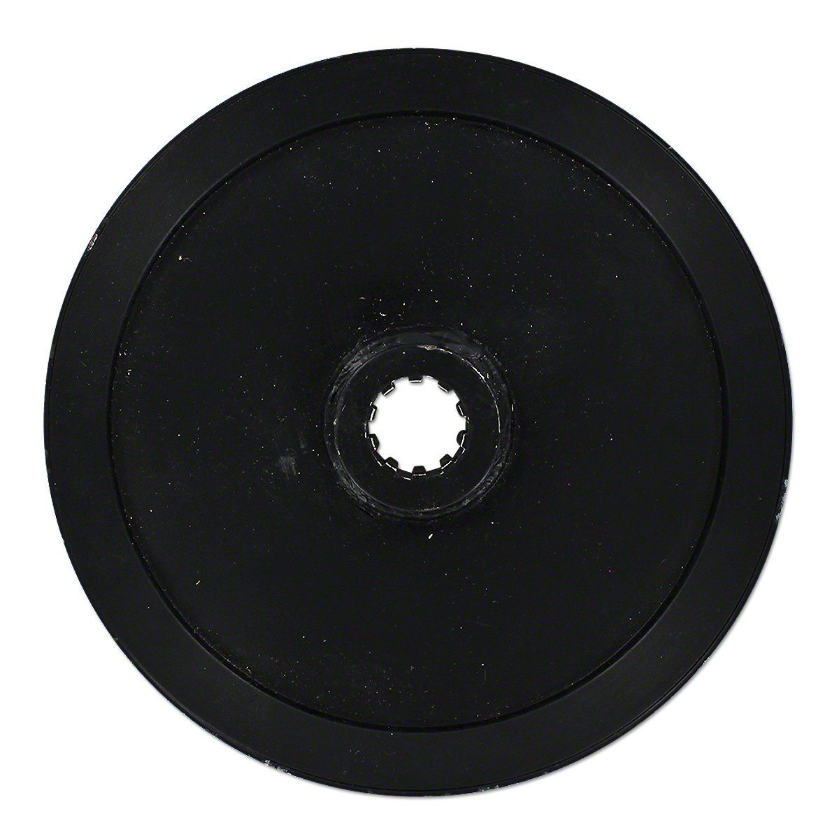 246900; all used as a steering clutch manifold oil seal), Loader / Backhoe: 210C (SN: 760731 and up; used as an inner rear axle essential oil seal), [ 300D, 310, 310A, 310B, 310C, 310D, 315C, 315D, 401, 401C, 401D, 410, 480A, 480B, 480C, 482C (all used as an inner back axle oil seal) ], 410B (up to SN: 704001; used as an inner rear axle oil seal)
– [ 1020, 2010, 2030, 2040, 2141, 2240, 2520, 2541, 2941, 3141, 3641, 4320 (all used as a PTO belt pulley shaft oil seal) ], 4020 (up to SN: 200999; used because a PTO belt pulley shaft oil seal), [ Crawler: 550, 555 (up to SN: 246900; all used as a steering clutch manifold oil seal) ], Loader / Backhoe: 315CH (all utilized as an inner rear axle oil seal); Replaces: AT124396, AT16887
– Fits: 55 (Sn: 3023 & up, As a diff. brake gear shaft seal); Replaces: 15874X
– Matches: [ G1000 Vista, G1050, G1350, G1355, G900, G950, G955 (As a 2 wheel drive inner front wheel seal) ]; Replaces: 10A26954
– Matches: [ 1865, 1870, 2055, 2155, 2255, 2270 (As a 2 wheel drive internal front wheel seal) ], [ 77, 770 (As a brake pinion shaft (bull pinion) seal) ]; Replaces: 1M-1110, 1M1110, M1110
– Fits: [ 100, 120, 125, 140, 145, 160, 2-135, 2-150, 2-155, 2-180 (As a 2 wheel drive internal front wheel seal) ]
Belt Pulley Gasket
Description
– Fits: WC, WD, WD45, WF; Replaces: 70202289
 3.43″ x 1.93″
 4 in. OD
 found in.
 shed device and functions like a turbine. Power transmission is proportional to the fill stage in the functioning circuit. As a consequence of the mechanical separation of the travel and pushed sides, the hydrodynamic coupling transfers the electricity put on-totally free and dampens the torsional vibration and torque shocks in the travel chain simultaneously.
 to 11000 KW
 of transport parts, hydraulic components, oil coolers and our very own monitoring system the Beegle. Do you want to know more about a product or have you got a question? Our specific sales engineers will always be happy to help you find the best product necessary for you technical problem. Feel free to e mail us if you possess concerns or seek information.
 way to locate your exact Omni Gear substitution gearbox is to use the six-digit assembly quantity stamped on each and every Omni Equipment gearbox.
 and belt.
 for your vacuum pump, and if you use our oil throughout the full guarantee period and follow essential oil change recommendations, we dual your warranty to two years!
 types. Would you like to discover more about our range of geared motors?
 potential drawback of this, however, is that backlash can make it harder to attain accurate positioning.
 individual velocity control requirements. Two adjustable rate drive models include a reversing lever that allows clockwise, neutral and counter-clockwise operation.
 drives are easy to install and simple to operate. Their higher level of efficiency also provides them a far more positive environmental impact.
 maintain these on the shelf as regular stock bores. However, we can supply sprockets with completed bores thanks to our fast-reaction internal industrial machine store. Typically our sprockets are manufactured out of 304 quality stainless, but 316 as well as a few various other grades are available upon request.
 low rpm, he or she will struggle as
 with reinforced hollow bore.
 driven system’s stop-start operation. Furthermore, water and chemical substances are evenly distributed over the crop.
 gearbox motors when from the same producer. The increased heat results in lower effectiveness and the parts ultimately wearing out.
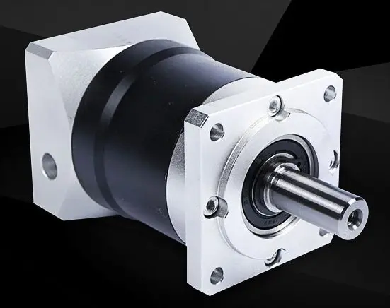 A carrier links the centres of both gears and rotates to carry one gear, called the earth gear or world pinion, around the additional, called the sun gear or sun wheel. The planet and sun gears mesh to ensure that their pitch circles roll without slide. A spot on the pitch circle of the planet gear traces an epicycloid curve. In this simplified case, the sun gear is fixed and the planetary equipment(s) roll around sunlight gear.
 high precision and torque.
  Quite a few DC Motors could be complimented with among our Worm Gearheads. ISL Products will continue to work with you to create and produce a Worm Gear Engine that may optimize the functionality of your unique application.
 1/6 – 25 HP
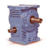 sliding contact reduces efficiency, it provides extremely quiet operation. (The utilization of dissimilar metals for the worm and gear also contributes to quiet procedure.) This creates worm gears suitable for use where sound should be minimized, such as for example in elevators. In addition, the use of a softer material for the gear implies that it can absorb shock loads, like those skilled in large equipment or crushing machines.
 practically all flat surfaces and prevents foreign matter accumulation or position fluid
 good shaft’s rotation. Straight pearly whites have similar features to spur gears and possess a large affect when engaged. They produce vibration and noise very similar to a spur equipment due to their straight tooth. The bevel gear has many different applications such as in a hands drill where they have the added good thing about increasing the velocity of rotation of the chuck and this can help you drill a range of supplies. Bevel gears are also within printing presses and inspection devices where they are manage at many speeds. Nylon bevel gears are usually used in electrical products such as for example DVD players.
 this case the worm truly behaves as if it had only 1 tooth around its circumference.
 substitute saving the client time and money.
 factor.
 ISO14001, OHSAS18001
 alignment of horizontal and vertical bases.
 ended or dual ended shafts to assemble in these gearboxes. All gearbox shafts are given keys and retainer bands.
 Combine the helical-worm gear unit with this AC motors:
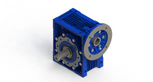 develop an all-new design that delivers the performance you need. Ask for a quote on a custom miniature gearbox or contact us to discuss your unique requirements.
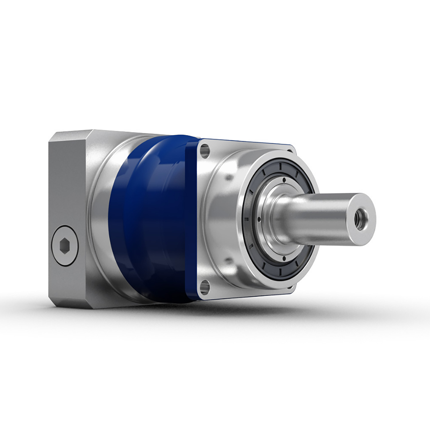
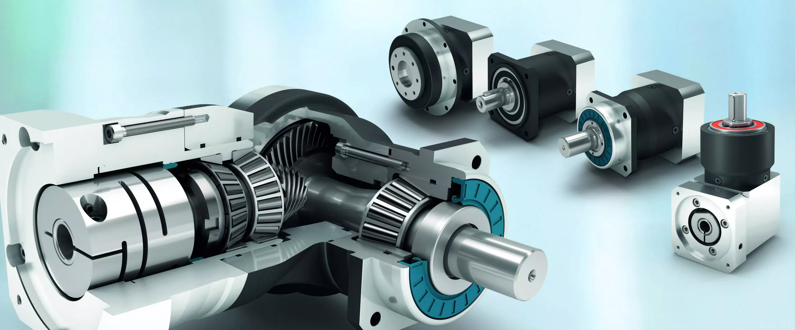
 the same size. All planetary carriers are manufactured as a cage made from solid material. This increases quiet operating characteristics while at exactly the same time improving positioning accuracy and reducing backlash. An additional shaft sealing ring ensures maximum dirt and splash water safety in accordance with protection class IP65 in all lines.
 90 degrees, the axial pitch of the worm and the circular pitch of the worm wheel will be equal. It is not uncommon for fine pitch worm units to have the size of the teeth specified when it comes to diametral pitch. The pressure angles employed depend upon the business lead angles and must be large enough to prevent undercutting the worm wheel the teeth. To provide backlash, it is customary to slim the teeth of the worm, however, not the teeth of the worm equipment.
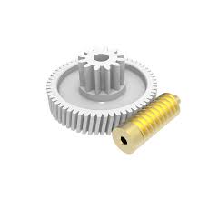 gears are manufactured for some of the very most demanding customers in the aerospace, security, and medical industries of today.
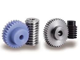 for speed reduction and raising the torque for electrical engine drives. You can tend to attach your NEMA engine to the reducer by using the NEMA C experience flange or work with a coupling. In the event that you desire a coupling for the output or input shaft observe our coupling section for selecting a coupling. We offer four assemblies left palm and right palm and double output shaft and shaft input and shaft result. Interchangeable with many worm gear manufactures. See info sheet in product overview for diamensions. Unless you see your type, you should Contact Us.
 and tooth cutting after the outside rim is usually cast around the center of the blank.
 knowledgeable in serious equipment or crushing machines.
 performance features and simplified maintenance. The usage of express of the skill helical and worm equipment combinations affords optimum efficiency fulfilling a multitude of ratio requirements. The EP is normally functionally interchangeable with the majority of major manufacturer’s drives.
 a housing with some bands that limit leakage. A breather can be a connect with a hole that is mounted in the gear housing allowing airflow and relieve inner pressure.
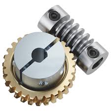 according to customer anticipations and in the highest quality. Learn more about it here.
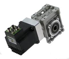 the guts distance between gears. As for pre-loading, this is often done utilizing a spring mechanism to hold the gears firmly set up. This also eliminates the play between your gear teeth and therefore eliminates backlash.
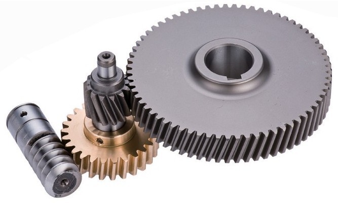 delicate acceleration adjustment by utilizing a big speed reduction is needed. When you can rotate the worm gear by worm, it is generally extremely hard to rotate worm utilizing the worm gear. This is called the self locking feature. The self locking feature cannot always be assured and another method is recommended for accurate positive reverse prevention.
 in Fig. 1. A two-stage system controlled by a two- stage thermostat enables more water to be applied on excessively warm, bright days. Temperature settings ought to be 5-10°F apart.
 enables more water to be employed on excessively warm, shiny days. Temperature settings ought to be 5-10°F apart.
 right size. Make sure that you add the set screw to hold the junctions tightly together. Place the pipe onto the plastic-type material that is lying out on the bottom. From there you will roll the pipe with the plastic-type until you have the beginnings of a roll-up forming.
 DC bus turns into “around” 650VDC. The actual voltage will depend on the voltage degree of the AC line feeding the drive, the level of voltage unbalance on the energy system, the motor load, the impedance of the energy system, and any reactors or harmonic filters on the drive.
 advanced microprocessors has allowed the VFD works as an extremely versatile device that not only controls the speed of the engine, but protects against overcurrent during ramp-up and ramp-down conditions. Newer VFDs also provide ways of braking, power boost during ramp-up, and a number of handles during ramp-down. The largest savings that the VFD provides is usually that it can ensure that the motor doesn’t pull extreme current when it begins, therefore the overall demand element for the entire factory can be controlled to keep the domestic bill as low as possible. This feature alone can provide payback more than the cost of the VFD in less than one year after purchase. It is important to keep in mind that with a traditional motor starter, they’ll draw locked-rotor amperage (LRA) if they are starting. When the locked-rotor amperage takes place across many motors in a manufacturing plant, it pushes the electrical demand too high which often outcomes in the plant paying a penalty for all the electricity consumed during the billing period. Because the penalty may become just as much as 15% to 25%, the cost savings on a $30,000/month electric costs can be utilized to justify the buy VFDs for practically every motor in the plant actually if the application might not require operating at variable speed.
 become positive or unfavorable at will and can hence generate any frequency that people want. So, we are able to make any phase maintain positivity, negative, or zero.
  polyvinyl.
 have to bring air flow price up. Besides, the soft movements caused by the supporters’ airflow also promote the strengthening of the vegetation’ stems and roots.
 not a single type of plastic that is most effective for a roll-up side. Rather there are a number of options with varying levels of durability, light tranny, and expected life.
 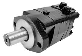 electric motor and a hydraulic pump are extremely similar. Because of this, some hydraulic pumps with set displacement volumes may also be used as hydraulic motors. A hydraulic motor works the other way round as it converts hydraulic energy into mechanical energy: a rotating shaft. It uses hydraulic pressure and movement to generate the mandatory torque and rotation. The energy produced by a hydraulic motor is determined by the circulation and pressure drop of the motor.
 maintenance options for motor needs.
 two front tires through the drive axles. The engine, transmission, and extra hardware is all positioned in the front side of the car.
 the greenhouse plastic and onto the roll bar. While there are various sizes of snap clamps offered, the hottest are those that fit over best 1.315″ OD (1 3/8″ top rail) tubing. Just click here to check the pricing of snap clamp
 arm or torque limiter.
 To see a complete summary of
  developed for make use of with the latest servo motors in applications that demand exact positioning and repeatability.
 worm speed reducers. Worm equipment reducers are used for speed decrease and raising the torque for electric electric motor drives. You can decide to mount your NEMA electric motor to the reducer utilizing the NEMA C face flange or use a coupling. If you want a coupling for the output or input shaft find our coupling section for choosing the coupling. We offer four assemblies left hands and right hands and double output shaft and shaft insight and shaft output. Interchangeable with many worm gear manufactures. Find data sheet in product overview for diamensions. Unless you see your type, please Contact Us.
  Rate Decrease; Fast Blinking = Reduced Velocity Setting
 inertia in gearbox selection.
 maintenance. A broad range of reduction ratios suit an even broader selection of specifications, while a variety of input shaft configurations maximize flexibility. In addition, the number of products that complement this series of gear drives make it a perfect choice for today’s industrial distributor.
 steel gear train and output shaft
 can easily build up inside the motor to harmful levels.
 Rated input
 improve rigidity and antiknock
 swiftness reducers. These gearboxes are created to manage varying loads with little backlash. Planetary equipment reducers operate more quietly than parallel shaft reducers. With 18 ratio options which range from 5:1 to 1000:1, we’ve a solution to suit your needs.
 engineered for encoder applications, Ever-Power micro inline spur gear drives are available in two frame sizes, and are rated for speeds up to 3,000 RPM. Light weight aluminum housings and stainless steel gears and shafts make these inline spur gearboxes tough and corrosion resistant, for your the majority of demanding applications.
 grinding procedure, thus stopping leakage of essential oil and entry of dirt.
 a zero backlash gearbox. The speed reducers are expensive, that reason their use is bound to automation solutions where efficiency and high precision are important to the level the cost ceases to be an issue.
 optimized housings of the helical bevel gears distinguish themselves by being machined on all sides and are therefore ready for a variety of installation options and applications. Various regular shaft executions and the double chamber shaft seals are ready for use.
 The materials and items use pass all the assessments laid down by the latest international standards, such as for example UNI EN ISO 9001.
 Radial Loads provided by High Precision Taper Roller Bearings.
 power is necessary than the system on the tractor can provide.
 according to your own requirements.
 motion is used in the purple result shaft via rollers or pins that interface to the holes in the disk. Like planetary gearing, the result shaft rotates in the contrary direction to the input shaft. Because the person parts are well-suited to 3D printing, this opens the entranceway to easily prototyping customized designs and gearing ratios.
 RomaxDesigner models may include spur and helical gears, and with the perpendicular-axis module, bevel and hypoid gears. The base software models gears with enough detail to investigate their effects on the rest of the system. Additional modules allow design and ranking to AGMA, DIN and ISO standards. For parallel-axis gears, additional modules permit macrogeometry definition and optimization for manufacturability as well as detailed evaluation of microgeometry for contact stress and transmission mistake. RomaxDesigner graphics are ideal for a variety of reporting illustrations, such as for example system topology and component deflection.
 and optimum torque (expressed in newton meters, N.m) that can be supported by each of their products. The torque density varies according to the gear reducer. For example, planetary gearboxes have a higher torque density.
 apparatus tooth areas, this lubricant is effective.
 be the increased torque that’s provided by adding an external gear ratio, there are many benefits beyond multiplying the torque output.
 for info associated to
 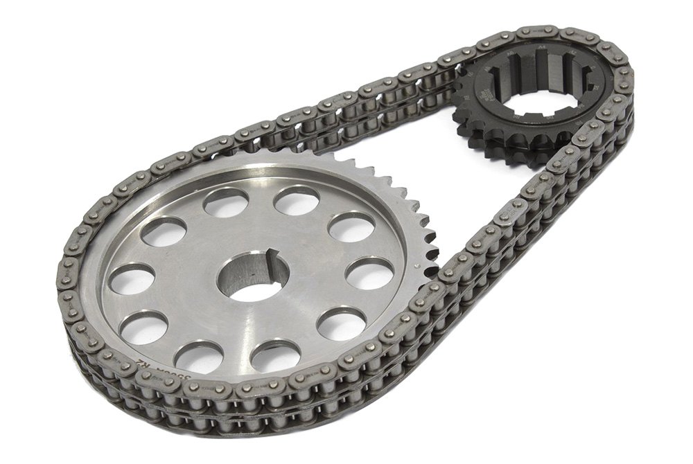 the ON/OFF key or switch. This causes a clockwise or counter-clockwise rotational movement on the motor program, depending on the desired direction of movement. This prospective customers to a movement of the networked gears and chain to go in the same path as the motor. Consequently, the chain conveyor movements the load through the drive train to the last gear, where off-loading is performed. For unidirectional operations, conveyor systems can also be tailor-made to provide movements to either path. This is accomplished through integrating two or more motors on either end of the conveyor program.
 series of short cylindrical rollers held together by aspect links.It is a simple, reliable, and efficient means of power transmission.
 size, quickness, lubrication, load, and drive support. A link belt silent chain contains removable links joined by rivets or interlocking tabs. These chains offer the advantage of set up without dismantling drive elements, reducing inventory, and raising temperature ranges
 the standard have diameters which range from 20 to 135 mm and axial distances of 17 to 80 mm. Furthermore, we offer custom worm gear pieces with diameters as high as 300 mm and center distances of up to 210 mm.
 to nearly every temperature change. Agricultural roller chain undergoes extensive examining and quality checks before it arrives at your farm. Try our agricultural smooth link chain for smooth operations every day. If you want trusted agricultural conveyor chain parts in a hurry.
 gears working with each other in tandem are called transmission or gearbox. Geared products will change the speed, torque, direction of a power resource.
 steel gears.
 is certainly 30 arc-minutes with choices for 4 or 8 arc-minutes. The NEMA 34 flanged gearbox has 440C Stainless steel bearings with seals and Nitrile o-rings shaft seals on both input and output. All fasteners are stainless steel. Hard anodized aluminium or 316 Stainless housings can be found. Customizing for apart from NEMA motors or your specific application is easily done.
 obtained.
 proper radiation against heat generated when products are operated at their maximum capacity
 protect the boom and the travel against inadmissibly large loads.
 as followings:
 the regular gear max. 1.5° degrees (two x .75°) in overall. The axial misalignment capability is restricted by the equipment teeth size in the sleeve and can be varied (optionally).
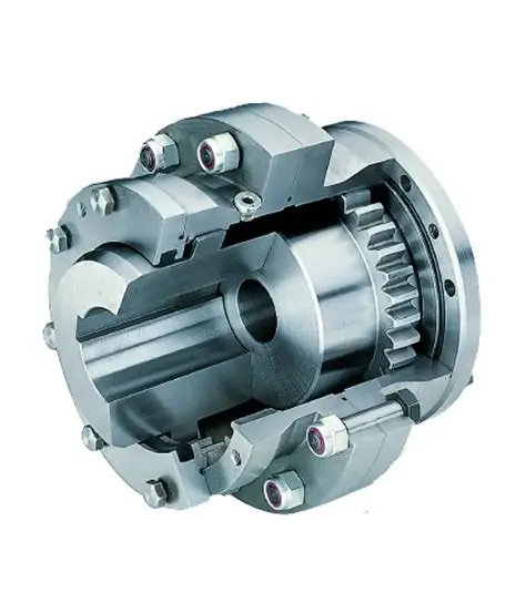 to angular misalignments, i.e., the angle of the spindle relative to the axes of the related shafts, of 4â5°. Common joints are capable of higher misalignments.
 jpg]#
jpg]# ry single motor.
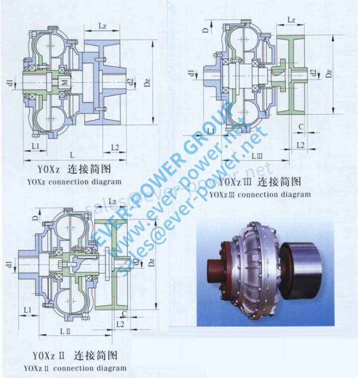 urces.
 our manufacturing device. We also welcome custom-made orders. Check out the price tag listing and the quotation with our firms and suppliers now.
 C or D
 switch system is installed within an integrated chamber and is certainly enclosed by an impact-resistant plastic material cover. The limit switch system is accessible and easy to adjust. The limit change system’s maximum switching range is certainly 40 or 64 revolutions of the drive shaft. The cabling is linked in spring-clip connections. The gearbox has an IP68 M16 x 1.5 cable gland (5-9 mm cable) for the cable feed-through.
 fashionable, slide flexible,
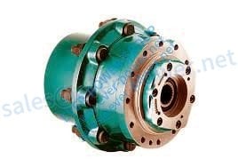 to provide our customers with a quiet and reliable product with excellent strength, lifespan and efficiency characteristics at an exceptionally attractive price.
 types: With key
 2.25
2.25 7KC
7KC and heat dealt with gears and shafts to ensure lengthy daily life. Four bolt mounting matches industry expectations. Each and every gearbox contains blade provider mounting nut and cotter pin. Gearboxes are transported dry and call for sixteen ounces of 80-90W gearlube or equal. Disclaimer: Any and all Original Gear Manufacturer’s (OEM) tradenames, trademarks, drawings, shades, descriptive details and portion figures are used for components identification purposes only, and DN Products, LLC (DN) is in no way implying that any certain elements are OEM parts. More, any use of the OEM’s tradenames, emblems, drawings or portion numbers by DN is created only to support
  a chain, which, in turn, drives a small sprocket on the axle of the trunk wheel. Early automobiles had been also largely driven by sprocket and chain system, a practice largely copied from bicycles.
 solid and efficient correct angle configuration, our correct angle planetary gearboxes offer a robust solution. The right angle bevel gearbox comes in 18 ratios which range from 5:1 to 1000:1, and it is back-drivable at all ratios.
 of compact and more reliable sun and planetary type of gears arrangement and also the manual clutch from manual power teach is definitely replaced with hydro coupled clutch or torque convertor which in turn made the transmission automatic.
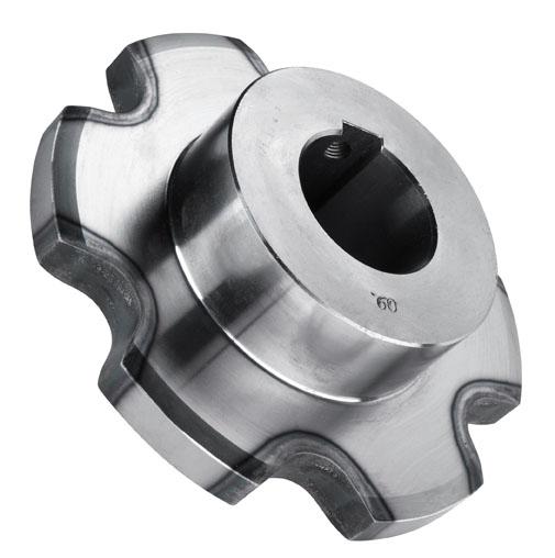 compared to a standard sprocket of the same pitch circle diameter and distribute use evenly across the teeth. If your conveyor chain is compatible, dual pitch sprockets are definitely worth considering.
 machine, icecream machine, sewing machine, kitchen equipments, etc.
 us know the thing you need and we can instruction you to the very best products on the market. We can also create any kind of custom products as per your needs.
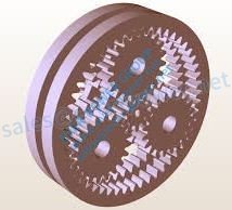 to improve input speeds and lower operational temps.
 Lock Weld-on Hubs are made from metal. Drilled, tapped and taper bored to receive normal Taper Lock bushes, The shouldered outer diameter offers a convenient method of welding hubs into lover rotors, metal pulleys, plate sprockets, impellers, agitators and many other devices which should be firmly fastened to the shaft.
 for confirmed envelope. The other significant advantages are simple and effective lubrication and a well balanced program at high speeds. The balanced planetary kinematics and the linked load sharing makes the planetary-type gearboxes truly well suited for servo applications.
 higher torque generation in comparison to among our spur gear motors. In turn, an EP planetary gear motor has the capacity to handle numerous load requirements; the more equipment stages (stacks), the higher the strain distribution and torque transmission.
 1996-1997 Dodge Grand Caravan 2.4L 3.0L 3.3L 3.8L
 Gearboxes are known by many different names, including gear drives, reducers, equipment reducers, quickness reducers, and gearmotors. All terms can be used more or less interchangeably when refering to inline planetary equipment reducers.
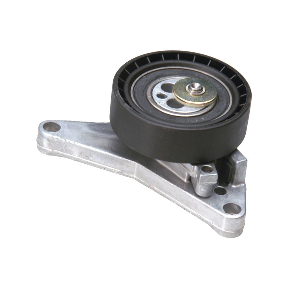 Bearing,Timing Tensioner….
 The force could be used parallel to, as regarding a hydraulic bolt tensioner, or perpendicular to, as regarding a spring-loaded bicycle chain tensioner, the tension it generates. The force could be generated by a fixed displacement, as regarding an eccentric bicycle bottom bracket , which should be adjusted as parts put on, or by stretching or compressing a spring , as regarding a spring-loaded bike chain tensioner; by changing the quantity of a gas, as regarding a marine riser tensioner; by hydraulic pressure, as regarding a hydraulic bolt tensioner; or by gravity acting on a suspended mass, as regarding a chair lift cable tensioner. In the power sector, the is a machine for maintaining constant pressure of the conductors during function of hanging the transmission network.
 V and W series. The G series includes a variety of
  V-belts are made from rubber or synthetic rubber stocks, so they have the flexibility to bend around the sheaves in drive systems. Fabric materials of various kinds may cover the stock material to provide a layer of safety and reinforcement.
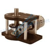 lubricated systems. Additionally it is not necessary to replace lubricant because the grease is intended to last the lifetime utilization of the gearmotor, eliminating downtime and increasing productivity.
 Casing painted with Grey color
 truck, or SUV.
 output swiftness ratio can vary from 1:1.4 to 1 1:7;
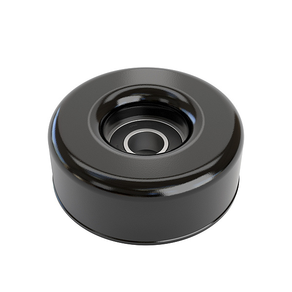 and then transmit rotation from one shaft to some other, in applications where it really is undesirable for connecting them directly. For instance, connecting a electric motor to the platter of a phonograph , or the crankshaft-to-camshaft gear teach of an automobile.
 order to guarantee the dependability of ventilation and display installations, Ever-Power introduced the EP engine gearbox – a compact and highly reliable self-locking drive that is developed particularly for use in horticulture. The Ever-Power EP is now the standard with regards to drive technology for cup greenhouses, and has a well-earned popularity for reliability, long support life and versatility.
 cast iron housing (SK02050 – SK43125)
 angles which are too big.
 to operator exposure to operating PTO shafts. Additional unsafe practices include mounting, dismounting, achieving for control levers from the trunk of the tractor, and stepping over the shaft rather of walking around the machinery. An extra rider while PTO electricity machinery is functioning is another exposure circumstance.
 can react. The fast rotation swiftness, operator error, and insufficient proper guarding make PTOs a persistent hazard on farms and ranches.
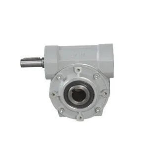 Imperial and metric sizes.
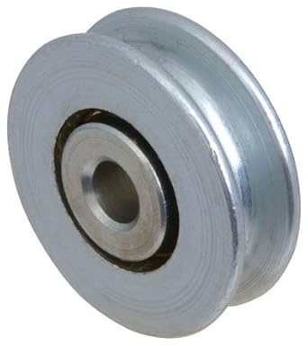 when the pulley body is a capped tube design.
 pipe materials and can be used to join pipes with equal or differing outdoors diameters (Up to 27mm). This makes the coupling perfect for joining PVC-O, PVC-M, PVC-U, GRP, ductile iron, asbestos cement, and metal.
 depends upon the lead angle and number of starts on the worm – and because increased efficiency is always an objective, the ratio should be kept as low as possible. To run properly, worms and worm gears used together must have the same diametral pitch and threads.
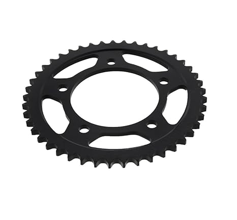 Every sprocket is usually checked and tested to ensure the highest quality and reliability to fulfill the needs of today’s high powered machines.
 of mechanical advantage. The spline style lets you rotate the torque arm lever to nearly every point. That is also useful if your fork circumstance is just a little trickier than normal! Performs ideal for front and rear hub motors. Protect your dropouts – acquire the Arc arm! Created from precision laser slice 6mm stainless 316 for good mechanical hardness. Includes washers to hold the spline section, hose clamps and fasteners.
 gate operator, parking barrier, wheelchair, electric vehicle, shopping cart software, water pump, floor polisher, vehicle lift, salt spreader, stair lift, hospital bed
 backlash and self-locking property
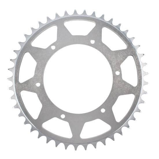 Aluminum Sprockets (0.250) 16T are extremely strong and light-weight. They are are .100” thick and accept standard .25” (1/4”) metallic or plastic chain.
 sprockets have a much higher tooth deflection than a standard metal sprocket does. This implies that several the teeth will bear the strain of the roller chain. With several teeth connected, this means that the load capacity of the sprocket will match approximately to the full functioning load of the chain.
 the camshaft and crankshaft turning at the correct rate. The crankshaft moves pistons up for compression and exhaust cycles, while the pistons move down for power and intake cycles. Based on the vehicle make, a timing belt may also run the water pump, essential oil pump and injection pump. The camshaft handles the starting and closing of the valves for intake and exhaust. The valves must open up at the correct time to allow gas to enter the chamber and close to enable compression. If the timing routine is off, fuel may not enter the cylinder or could escape through an open up exhaust valve. If the valves aren’t fully closed during compression, a lot of the engine’s power will be lost.
 sizes
sizes sprockets are able to withstand higher capacities because there is more surface contact between the rotating parts. Surprisingly this design also uses less friction and is more stable when mounted onto the shaft.
  until there is absolutely no lubricant film still left, and for that reason, the worm rubs at the metal of the wheel in a boundary lubrication regime. When the worm surface leaves the wheel surface, it picks up more lubricant, and begins the procedure over again on another revolution.
 and/or cheaper viscosity lubricant in transmitting systems. Consequently, tapered roller bearings in transmissions are being subject to increasingly severe lubrication conditions, increasing the risk of lubrication oil film depletion (lean lubrication circumstances), surface damage, and bearing seizure.
 in acute cases, they may select angular contact or tapered roller bearings, both which are created to withstand axial loads.
 of energy absorbing elastomeric isolators that limit the transmission of structure-borne vibration and impacts. Our products are made for simple use and a multitude of orientations in compression, shear and slanted angle loading. While economical, the products are made of quality rubber, silicone, Neoprene and steel components that enable support for the proper amount of load for every software. Filter through our in-depth product listing of elastomeric products including base mounts, cup mounts, bumpers, bushings and grommets to find the right remedy for your application.
 We employ latest equipment to design the products at par with the international standards. Available in various sizes & dimensions, these can be customized as per the requirements of the clients.
 and securely. However, with power locks, you press switch and all doorways in the vehicle lock simultaneously. The energy of this is through a lot of things including your car battery as well as your door lock actuator. A door lock actuator is atlanta divorce attorneys solitary door of your automobile. That is why, when one door lock isn’t working properly just how it should then chances are because of the entranceway lock actuator. When the vehicle component is certainly faulty, it normally only influences the single door in which it is specified to utilize. When your door lock actuator venture out and have to be replaced, the entranceway panel of the door will need to be removed in order to reach the entranceway lock actuator comfortably and easier. Understand that this won’t be easy as most door panels are incredibly difficult to log off. The important matter here is understanding that your door lock actuator is definitely important. It may well not seem like a crucial auto component for your automobile but you require it properly employed in order to securely lock your automobile when you receive out to go in to the store, the mall or even when you go back home from do the job or college. Locking and unlocking your vehicle manually if you have ability locks can be extremely frustrating. You can often neglect to manually lock it if you are very much accustomed to pressing just a little press button and it performing all the hard operate for you personally. If this happens to you, you are inserting yourself in the threat of turning into the prey and victim of theft.
 metric,climax clamp collars and couplings metric shaft upon metallic s kw stainless,climax metallic products drill kit movement industries collars and couplings clamp threaded shaft,climax clamp collars steel products 2 1 ” bore size and couplings metric shaft,climax collars and couplings clamp china family pet sound color collar collection nylon puppy metric shaft,male mature taste sexual activities husband wife climax share long lasting collars and couplings metric shaft clamp,buy climax metal a series two piece clamping collar clamp collars threaded shaft and couplings.
 in an electric furnace. Grade 100 Chrome Steel, when formed in this manner, includes a sphericity of 0.0025mm and a hardness of HRC 60-67.
 a series.
 gearbox is known as right-angle when it only has two shafts (input and output),
 manufacturers need to account for axial thrust. Nevertheless, the fact that the helix angle may differ from 15 to 30 degrees permits flexibility with regards to design. They are found in in-line applications as well as parallel shaft applications.
 Taper on Barrel – Self locking taper provides the highest degree of mechanical locking product to product.
 sprocket, failure to engage will lead to chain jumping in addition to excessive wear. Something vital that you note is certainly that with chain sizes C2040, C2050, C2060, C2060H, C2080H, C2100H, C2120H, and C2160H when the tooth count can be 31 or even more you can use a standard roller chain sprocket. This guideline does not connect with carrier roller style chains which where the roller diameter exceeds the sidebar elevation, these chain sizes consist of C2042, C2052, C2062, C2062H, C2082H, C2102H, C2122H, and C2162H.
 necessitate rolling component bearings. Small planetaries can often manage with low-price sleeve bearings or various other economical types with fairly low axial and radial load capacity. For larger and servo-grade gearheads, durable output shaft bearings are often required.
 gives a tighter suit and increased keeping power, without the typical shaft damage connected with arranged screws shaft collars.
 form of electric motors. Thus the gearhead can be close in diameter to the servomotor, with the output shaft in-line.
 contact ball slewing bearing: without equipment bearing (non tooth), exterior gear bearing (exterior tooth), and Internal gear bearing (internal tooth).
 worm gear sets based on the Framo Morat standard have diameters which range from 20 to 135 mm and axial distances of 17 to 80 mm. Furthermore, you can expect custom worm gear sets with diameters of up to 300 mm and center distances of up to 210 mm.
 Kinematics’ ZE zero-backlash slewing drives were created with this patented hourglass worm technology, maximizing total gear contact while eliminating the deadband. This innovative design delivers unprecedented degrees of positioning accuracy, extraordinary operational reliability, minimal temperature generation and superior acceleration control in these extremely demanding engineering applications.
 120 lbs / 133 to 489 N depending on the collar bore size. In situations where higher holding ability is certainly or clamp axial load is required, the quick-clamping collar isn’t the recommended decision. EPT offers a complete type of industry-leading one-part and two-piece shaft collars created for these applications.
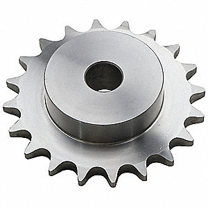 sprocket” is usually a set sprocket plate-wheel with no hubs that extrude on either side.
 split into a traveling sprocket and a driven sprocket. The driving sprocket is mounted on the engine output shaft by a spline; the driven sprocket is certainly mounted on the motorcycle driving wheel, and the power is definitely transmitted to the traveling wheel through the chain. The drive sprocket is definitely smaller compared to the driven sprocket, which can reduce the speed and raise the twist.
 isn’t restrained. For instance, when you must lift the jack to meet up a load. This is how they work: An integral, set to the jack housing and inserted right into a keyway milled in to the length of the lifting screw forces the lifting screw to translate without rotating.
 center of an air compressor may be the screw element which can be called air-end. The air-end is the most important part of any screw-type compressor. It’s that section of the machine where in fact the actual compression takes place. It is the heart of the rotary screw air compressor.
 only practical, ideally under ten-to-one. A
  they require some shade you then should become sure to place your greenhouse underneath some trees. Remember that you will most likely end up needing to get a building permit before you begin on your greenhouse. Get with a building inspector to get all the necessary details before you begin building.
 or indexing tables, pinion gears, pulleys or other drive components with no need for a coupling. For high precision applications, backlash amounts right down to 1 arc-minute can be found. Right-angle and input shaft versions of the reducers are also available.
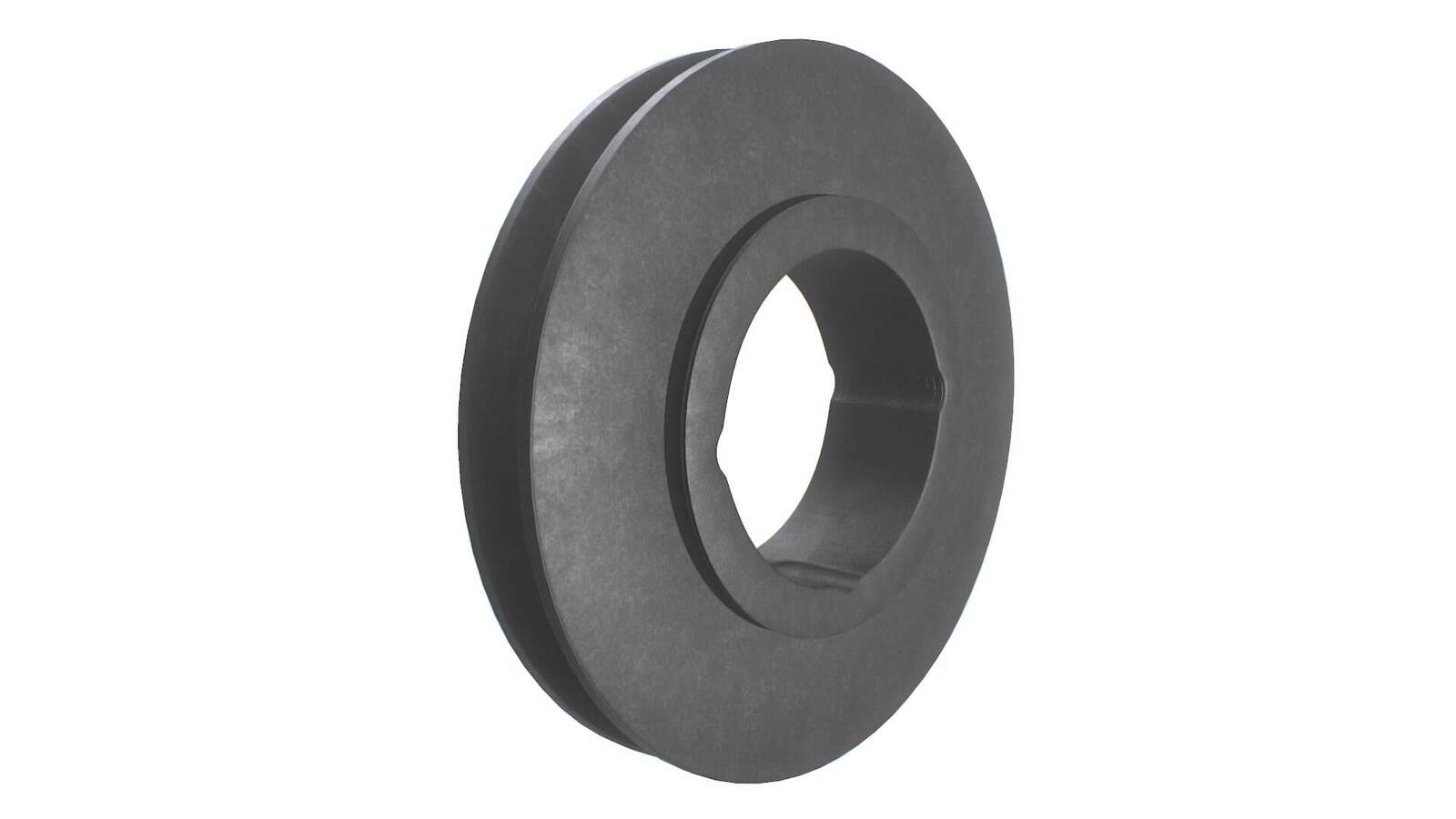 sizes like Taper bush 2517, 3020 taperlock and 1610 taper lock bushing and numerous additional sizes.
 ratio. This means the gearbox uses 4 percent much less energy to move the device through the field, but, moreover, the design has a completely recessed tooth action. With a completely recessed design, the gears keep lubrication oil between the gears longer, reducing friction for increased load capability and longer life.
 within the driveshaft may cause the faltering acceleration. You may also hear sounds as the car is certainly shuddering from the worn-out U-joint. You’ll want such issues tested as soon as possible by a qualified mechanic.
 more advanced than the start-stop microswitch design used with single-speed electric motor drives.
 is vented to the reservoir. With fluid pressure to one aspect of the piston and none to the various other, the piston techniques which in turn movements the rack and causes the wheels to carefully turn. When the tyre is certainly released the rotary valve returns to neutral, pressure equalizes and the turning of the tires stops. The power steering pump is made to provide adequate circulation when the engine is certainly idling. Consequently, the power steering pump moves much more fluid than required when the engine is usually running at faster speeds. The energy steering pump contains a pres-sure relief valve to make sure that the pressure does not get too high at quicker engine speeds when therefore much power steering fluid is being pumped.
  its power. Since torque is applied directly to each axle, there is absolutely no spider gears, which will be the weak spot of open differentials.
 one stop store and give you a free of charge quote in only seconds.
 with roll-up sides it is possible to replace the sides without changing the top cover. Simply something to keep in mind.
  the exclusive learn distributor of Hyundai Electric’s low-voltage motors. Providing fast, often same-day time, shipping from six regional All of us warehouses, WorldWide Electrical takes pride in providing a competitive edge to your customers by giving an answer to their requirements with urgency, technical experience, and professionalism.
 sprockets quickly the shelf for instant delivery. Our metric sprockets are usually supplied as standard steel with heat-treated tooth (up to 30 tooth) and stock bores. When a sprocket has heat-treated hardened the teeth, it typically lasts longer and performs much better than those that don’t. We also stock various finished metric bore sprockets, but if we don’t possess it on the shelf, our in-house machine store can re-bore the sprocket. We likewise have sprockets with completed bore configurations, taper bushed design, QD style and different materials (plastic, stainless and more). We also produce custom metric sprockets upon ask for with an instant turnaround.
 The system is liquid driven by the energy Steering Pump. The Power Steering Pump forces high pressure onto the Steering Hose, which links to the Rack and distributes liquid to greatly help with lubrication for the shifting components.
 place a mesh display. The mesh facilitates the Turface
  systems.
 more powerful, more reliable, and go longer than aluminum racks.
  rod end, which is attached to the spindle.
 bearings, optional lubricants for intense temps, and Delrin gears for reduced noise. Shortened housings are available for select ratios.
 help the steering rack move as you turn the tyre so it isn’t so hard for you to turn your wheels when your vehicle is moving slowly or halted. Like any high-pressure hydraulic system, the power steering system used with your rack and pinion can be prone to leaks.
 is more challenging
 electrical motors.
 of a more substantial greenhouse with a typical tractor, and a smaller greenhouse by simply two individuals.
 kneewall under the curtain system. This will keep flying debris away from the bottom level. It will also keep a standing up snow from leaning against the curtain. They are obtainable in 6′, 8′ or 12′ systems. Make sure you contact us for a
  to both types as a “taper lock” because they both utilize the tapered wedging action to lock to the shaft. The taper bushing, with it’s straight sides, runs on the set screw to drive the bushing in to the bore of the component being set up (sheave, sprocket, etc.). Be careful when installing these screws. The holes with threads on the bushing are for removal just. Also be aware that the appearance of a flange on the outside of the bushing doesn’t indicate it’s a QD design. Split Taper bushing also has a flange, and both aren’t interchangeable. The QD style includes a split that continues through the flange. The Metal QD (Quick Disconnect) Type bushing offers versatile and easy set up while providing exceptional keeping power. QD Bushings are used considered the industry offering convenience and design versatility. They are precision machined of quality Steel and are set up by tightening many cap screws. This draws the bushing into the taper bore of the product which compresses the bore of the bushing. QD bushings are easily removed utilizing the cap screws as jack-screws. Dual drilled holes are furnished in QD Bushings permitting installation of product in the traditional or invert positions. This allows cap screws to become installed through product hub or bushing flange whichever is most convenient. A substantial benefit in installation, cap screws are often inserted from the exterior where they are often accessible. QD Bushings can be found from stock with all well-known bores within the range of every size bushing.
 the temperature and humidity of your greenhouse. In addition, it gives you side access to both your low and high tunnel hoop homes. It’s even easy to install; just follow these instructions for guidance on how to integrate this greenhouse curtain crank into the creation of your greenhouse.
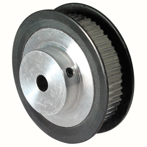 mounting, for simple and quick installation
 harm. utilized a plastic put on ring without the supporting composition around the wear ring. The travel shaft splines also visit a lot of wear with
  surface coated by painting, colorfast. The inner gears are made from high quality pinion steel treated by carburizing, high hardness,no damaged of teeth and long service lifestyle Top quality sealing pad can be used for the shell,good aging-resistance and waterproof. Power indicator of double shades is configured to verify the power and its whirling orientation conveniently.
 Though the volume ofgreenhouse space that’s heated is decreased, the amount of cold air flow ismaximized. This helps it be harder to mix and reheat the air flow above the machine whenit uncovers in the morning. Retrofitting may also be a issue if the gaslines, electric conduits and heating system pipes are installed at gutter level.
 master shield is attached to the tractor and extends over and around the PTO stub on three sides. This shield is made to offer coverage from the PTO stub and the front joint of the travel shaft of the connected machine. Many tractors, especially elderly tractors, may no more have PTO learn shields. Expert shields are taken out or are lacking from tractors for several reasons including: harmed shields that should never be replaced; shields taken out for convenience of attaching machine travel shafts; shields taken off out necessarily for attaching machine travel shafts; and shields missing when used tractors are sold or traded.
 number of commercial systems can be found, growers can assemble and install their own system using a high pressure piston pump and fog nozzles. The basic components are proven in Fig. 1. A two-stage system managed by a two- stage thermostat enables more water to be employed on excessively warm, bright days. Temperature settings ought to be 5-10°F apart.
 have light-weight roof vents and could require a more powerful vent opener to keep them closed or prevent them getting blown away – check
  can last up to 20 years.
 the correct amount of ventilation into the greenhouse and closes when the temperature cools. The vent arm was made with a metal cylinder that contains wax which expands when heated to force a piston, which raises the home window, as the atmosphere gets warmer, then contracts since it cools, closing with the use of a spring and resetting the piston. All you have to to do is to install it on your roof vent window and it instantly starts functioning. The Automatic Vent Opener functions without the usage of electricity and is compatible with all
  protect your plant life. With UV protection, it diffuses the harsh rays of the sun while keeping heat inside, producing a temperate greenhouse. We focus on geosynthetics and greenhouse plastics for different agricultural applications. BTL Liners offers a variety of designs and configurations that you can choose from please contact us; we are pleased to discuss your project and support you in finding what you need.
 from the insulation. The space between the liners holds the perfect amount of atmosphere to keep a constant temperature and great insulation, and it is a suitable buffer from the wind. The bottom line is, if you are looking for a multi-season greenhouse with a comfy environment for you plants, you might want to consider an inflated dual polyethylene cover greenhouse. Greenhouse plastic on its own, is not very insulative, but when you inflate air between two layers you provide extra insulation and the greenhouse will retain its temperature into the night. This technique also assists your greenhouse structure by protecting during less than desirable weather conditions. You will get the most bang for your buck with the features you have to keep your plants content.
 crucial to pick the right agricultural chain for your equipment. Fortunately, the educated staff at Shoup Manufacturing can guide you through the many types of agricultural roller chains, agricultural metal detachable chains and agricultural manure spreader chains that people carry. Our high quality parts are provided by top notch manufacturers, and our shipping specifications ensure that your purchase will arrive quickly.
 the shaft. will not employ PTO driveline shield retention chains on our goods.
 listened to the wants of our buyers and placed the greasing nipple at wide-angle PTO’s into the cross bearing. The different novelty, we launched with wide-angle PTO travel shafts is in line greasing. We wished to additionally simplify the repair and extend the lifespan of joints.
 put into practice and free wheels efficiently when apply exceeds tractor PTO speeds. All measurements are nominal.
  a
a  of powerful motors to choose from in an array of cooling and lubrication configurations. And we lead the industry in lead moments for delivery; Please be aware that we possess the capability to provide custom styles to meet your specific power curve, speed performance and user interface requirements. The tables below are performance
  voltages can be an increase of up to 2.5 times the motor’s nominal voltage. This stresses the electric motor
  system demand.
 shutdown methods and wait for every moving parts to stop before getting off the tractor or approaching the attachment.
 in bore sizes from 19 to 500mm, Power-Locks can mount any rotational component.
 Our helical gear devices are used wherever high torques are required.
 or a mixture of both possible
 a look at both the current waveform and the current spectrum. In the web pages that follow, some examples of problems discovered in DC drives and motors are presented.”
 business lead tolerance is approximately ±0.004″ per foot.
 with load handling capacities from 1/4 ton to 100 tons. They might be used individually or in multiple arrangements. There are no “regular” travel lengths and all Worm Gear Screw Jack systems are designed to specification.
 formed, typically using Class 2-C (Centralizing) tolerances. Jack lift shaft business lead tolerance is approximately ±0.004″ per foot.
 the Gates Made-to-Purchase Metals team could work with you to create a custom engineered option.
 be found either motorised or with an insight shaft assembly.
 it begins to unfold, the windowpane begins to open up. To close a home window, the arm begins to fold back again up into its original position, bringing the windowpane to a close.
 be low cost with easy set up. As this kind of they quite common whatever the simple fact that clamping collars have been around for some time. Setscrew shaft collars are still prevalent in today’s applications that don’t need post-installation changes and where price is a concern.
 JUST LIKE THE NAME TO WORK & PERFORM SMOOTHLY GOING UP & DOWN WHEN WORKING WITH YOUR WINDOW.
 operating.
 Service Bulletin) whereby a set of shims and larger shank diameter bolts were installed to take up the space between the subframe and the body, limiting subframe motion and tightening the clamp load on the subframe. However, the noise and shifting subframe issue can still return with these shims installed.
  acting”.
  Gear Motor – 3-Stage
 the car until it’s repaired. The ignition lock itself can’t be repaired and must be replaced,
  takes place
  dust,
dust, internal metal or Kevlar cords. The most typical tooth geometry for belts in linear actuators may be the AT profile, which includes a big tooth width that delivers high resistance against shear forces. On the driven end of the actuator (where in fact the motor is definitely attached) a precision-machined toothed pulley engages with the belt, while on the non-driven end, a set pulley simply provides guidance. The non-powered, or idler, pulley is often utilized for tensioning the belt, even though some designs provide tensioning mechanisms on the carriage. The kind of belt, tooth profile, and applied tension pressure all determine the pressure that can be transmitted.
 Our clients can get this product at marketplace leading prices.
 pulley to go the same load.
 positioning for an excellent clean and sterilization.
 also required this because their important clients demanded that their machines maintain accurate positioning with no error compensation on the axis.
 the collet, leave 15mm of mandrel from the collet to the mounted bit for ultimate performance.
 to discover more about our Lifetime Warranty and also to register your product online.
 end result spline count.
 – KRHGF – KRHGFD) : Excellent products with high precision and strength, and low sound and abrasion characteristics.
  well as for muling cables. They have already been designed for light weight applications only and are available in either a horizontal or vertical configuration. Up to 24 lines can be accommodated. Ceiling, wall, or pipe mounting available. Mule sheaves include 3″ diameter sleeve-bearing wheels and painted metal housings. When built with optional ball-bearing wheels, Mule sheaves can be used for the increasing and decreasing of light-weight scenery. Solid nylon or steel ball-bearing tires are obtainable at an extra charge.
 steel cage
  is constructed of plastic and is definitely RoHS compliant. The gear ratio could be adjusted according to the buyer’s requirements.NFP-motor manufactures all kinds of micro dc motor for over a decade. Motors produced by us are trusted in different applications, such as telecommunication devices and health-care products, medical products and robotic products. Monthly capacity over 15 million motors. We have been making the best attempts to become one of the leading micro motor manufacturers in this sector. By investing 10 % of our annual revenue into R&D along with advanced services, we continue to grow stably. Our objective is to produce cost effective motors with best value to fulfill our customers from worldwide. This is the target we aim at now and forever.
 a conveyor belt system, and the hobby craft sector to hold wheels on axles in handy remote control vehicles, among others.
 machinery. However, also, they are used in steering systems to improve the direction of vehicles. The features of rack and
  slope for casting ejection, internal measures diminishing circulatory towards enclosure bottom level by 1°
 both situations.
 remote drive and end result trains. Cardan shafts from Ever-Power offer suited mechanical drive alternatives in nearly all industrial sectors because of their versatile style and their high productivity.
 required gear design. These versatile gears are better suited to use with great instrumentation and additional small-scale elements, and in high precision applications.
 the same gear. (The difference between your two designs is that double helical gears have a groove in the centre, between the teeth, whereas herringbone gears do not.) This arrangement cancels out the axial forces on each group of teeth, so larger helix angles may be used. It also eliminates the necessity for thrust bearings.
 pulleys to your drawing specifications
 path of the rotation depends upon the various physical parameters of the machine: vibration frequency and amplitude, cord tension, and the radius and moment of inertia of the pulley.
  vibrations.
 that you can cater the particular needs of the customers.
 square protrusion for a wrench or socket. Using the appropriate tool, release tension on the belt. You’ll need to hold some spring tensioners while slipping on a fresh belt. Others may possess a locking mechanism, such as a hole for a locking pin or hex key.
 long lasting stainless steel construction is perfect for food and beverage applications or where non-corrosive sprockets are had a need to prevent rust.
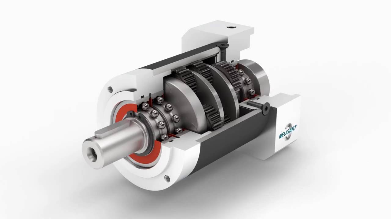 the effective torques, the force measurement measures the deflection of bending beams. Inductive rate sensors on all drive gears permit the speeds to become measured. The measured ideals are transmitted right to a Computer via USB. The info acquisition software is roofed. The angular acceleration could be read from the diagrams. Effective mass occasions of inertia are dependant on the angular acceleration.
 accurate, and don’t need re-tightening.
 – Suits: [ S, SC, SC-3, SC-4, SO (As a differential brake pinion shaft seal) ], [ Super 400, 1030, 1030 Comfort King, 1031, 1032, 1070, 1090, 1170, 1175, 1200TK, 1270, 1370, 1470, 1570, 2090, 2290, 2294, 2390, 2394, 2470, 2590, 2594, 2670, 3394, 3594, 400, 401, 402, 403, 405, 410, 411, 412, 413, 414, 415, 425, 4490, 4494, 4690, 500, 520, 610, 620, 700, 701, 701B, 702, 702B, 703, 703B, 705, 705B, 710, 710B, 711, 711B, 712, 712B, 713, 713B, 715, 715B, 725B, 730, 730CK, 731, 732, 733, 734, 740, 741, 742, 743, 744, 770, 800B, 801, 801B, 802, 802B, 803, 803B, 805B, 810, 810B, 811, 811B, 812, 812B, 813, 813B, 815, 815B, 830, 830 Convenience King, 831, 832, 833, 840, 841, 842, 843, 870, 900, 900B, 910, 920B, 930, 930 Ease and comfort King, 931, 932, 940, 941, 970 (all used as a front crankshaft essential oil seal) ], [ Cruz Air: 45, 45B (all utilized as a front crankshaft essential oil seal) ], [ Excavator : 40D, 40E (all utilized as a front crankshaft essential oil seal) ], Industrial: W7C (all used as a front crankshaft oil seal on rubber tired loaders); Replaces: A157044, A23433, A24715, A27838, A40349, A57342, A62049, O3866Abdominal, O8583AB, O9708AB, T34263
  of the most noticeable benefits of helical gears over spur gears can be much less noise, especially at moderate- to high-speeds. Also, with helical gears, multiple teeth are at all times in mesh, which means much less load on each individual tooth. This outcomes in a smoother changeover of
  making them much sought after in the industry. Consequently our geared motors tend to be to be found as part of our customers own devices.
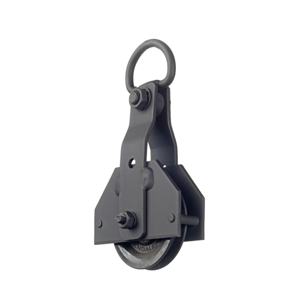 that your bike lugs around at low speeds, you might should just alter your current equipment ratio into something that’s more ideal for you.
 to be transmitted to a couple of traveling wheels, dividing the force equally between them but permitting them to check out paths of different lengths, as when turning a corner or traversing an uneven road.
 type of bevel gear is named external since the gear teeth point outward. The pitch areas of meshed external bevel gears are coaxial with the apparatus shafts; the apexes of both surfaces are at the idea of intersection of the shaft axes.
 in a variety of shapes and sizes for your capability of choice. We have been
  bought the best oil surroundings compressor with two oil filter. So as to reduce some drinking water and dirty.
 in dirty and explosive environment. Slip s is the imp element in this kind of motor.
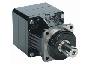 parameters
 and input shaft versions of these reducers are also offered.
 energy into mechanical energy. It functions by using a single-phase power supply. They contain two types of wiring: sizzling and neutral. Their power can reach 3Kw and offer voltages vary in unison.
 winding. When the stator can be fed with an individual phase supply, it produces alternating flux (which
  are available in a variety of configurations. The two main types of hydraulic cylinders are Tie-rod and Welded. Each one of these cylinder types can have unique applications due to their
  multi-joint, isolation and core exercises to be performed.
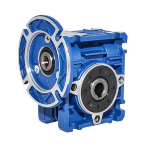
 they are permanent-magnet synchronous motors, or PMSMs, that rely upon magnets built into the rotor.
 HVAC control systems, and also to power pneumatic tools.
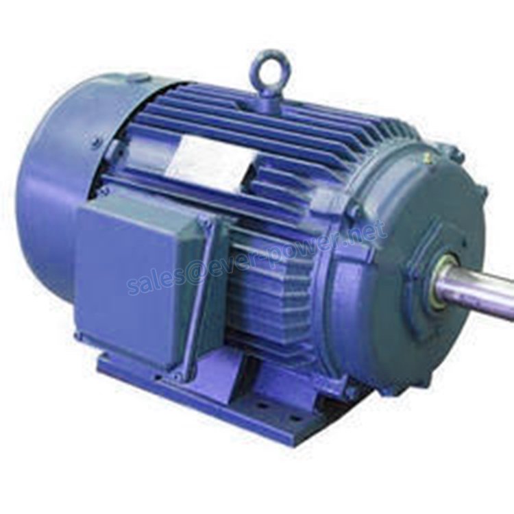 any moving contacts, which eliminates sparking
 gearheads perfect for servo applications
 be created with a low price point.
  stop in a safe style, without damaging the engine.
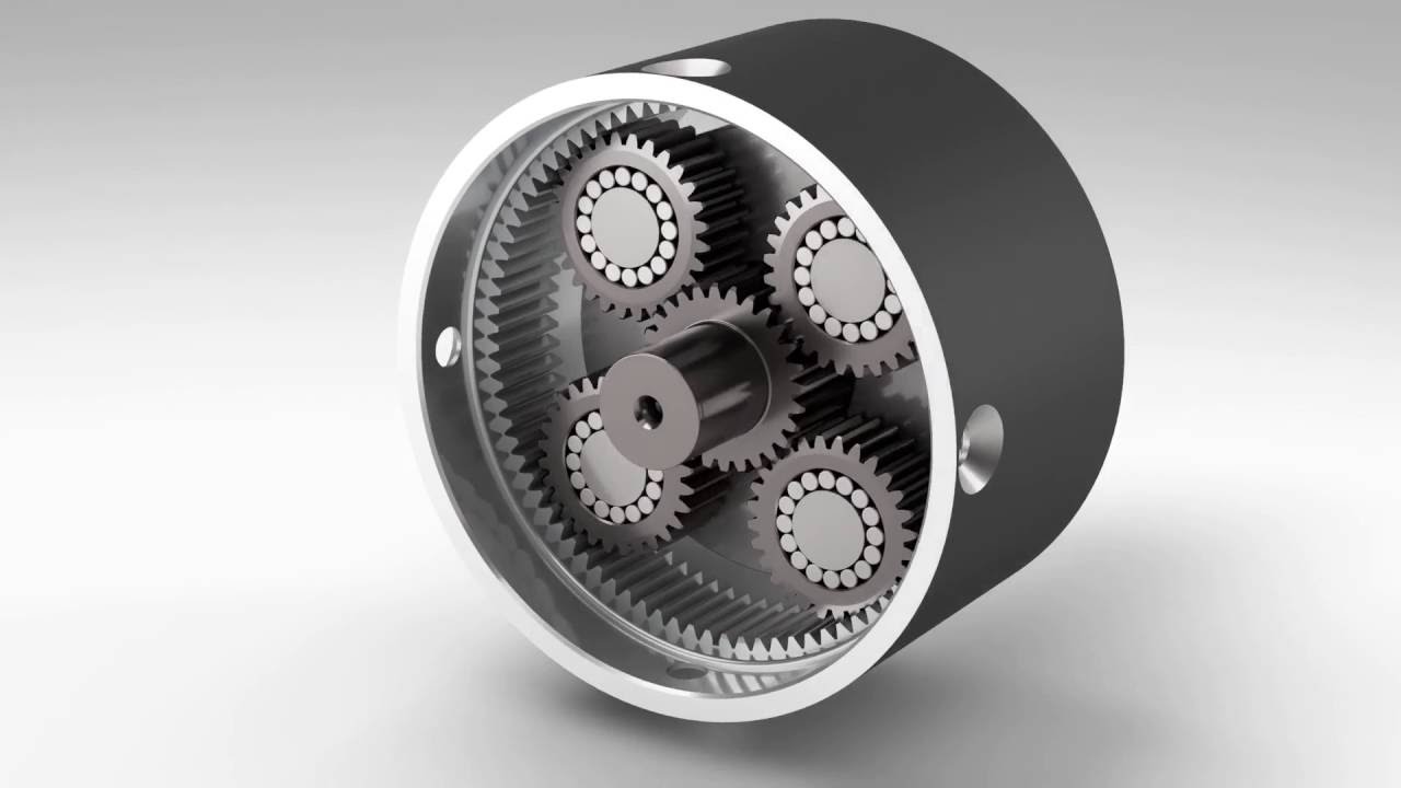 of the planet gears and is responsible for final transmission of the result to the outcome shaft.
 optimal range to ensure that the motor to use efficiently. Roboteq AC Induction controllers can be configured to operate in another of three modes:
 Marine.
 be the component of the hydraulic system that takes mechanical energy and converts it into fluid energy in the form of oil flow. This mechanical energy is taken from what is called the primary mover (a turning drive) such as the power take-off or directly from the truck
  welded design. Welded cylinders are typically a
  open center hydraulic systems. Gear pumps trap oil in the areas between your the teeth of the pump’s two gears and the body of the pump, transportation it around the circumference of the apparatus cavity and then force it through the wall plug slot as the gears mesh. Behind the brass alloy thrust plates, or use plates, a small amount of pressurized oil pushes the plates tightly against the apparatus ends to improve pump efficiency.
 also expedite development of
 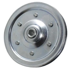 for internal compensation weight in profile 90 x 90 L
 more coils, the more powerful the motor.
 equipment, and home appliances.
 control switch. All of the wiring in the middle of your electric engine, capacitor and quickness control change is still installed nevertheless the cord itself is normally detached as seen in the photos. (Discover “Control Notice” below for alter type.)
 constructed of high performance plastics.
 the most economical choice would be a Three Phase Induction motor accompanied by a BLDC motor. I would suggest BLDC ( for its huge marketplace penetration recently,ease of
  reliability
 roll-forged sheave is available in the following: ordinary bore, bronze bushed, roller bearing, tapered roller bearing, lubrication thru hub, important ways, set screws, total complement bearing.
 recycleables (oil, gas, air, drinking water, metals, and nutrients) into a lot more than 70,000 different items.
 systems. Required gas flow rates for these procedures is increasing.
 Werther International’s goal is certainly to meet the high criteria demanded by the medical and oral industry. Our atmosphere compressor items deliver the quality of air needed to keep instruments clean as well as your patients secure. A dental surroundings compressor is a vital part of a dental office that must definitely be reliable and in a position to withstand everyday use. Medical grade surroundings compressors are accustomed to drive pneumatic devices in surgical areas, vital care areas, nurseries, operating areas, intensive care, post-operative treatment, emergency areas and more.
 torque they are able to bear. Nevertheless, we can find certain regulations governing these parameters.
 but stream of air was extremely weak. It is sufficient if all you want to accomplish is engrave,
  operated lifting apparatus- air hoists can be utilized for a variety of lifting operations
 and the winch. This cuts the direct pull load in half, which doubles the number of fat your winch can pull.
 The single stage alternating current motor is much less reliable and more costly to be used in a national electricity grid in comparison to 3 phase alternating current motor.
  can certainly run the electric motor on virtually any home current, but it’s improbable to be as powerful as a three-phase version. Three-stage motors can pull more power securely and with a far more efficient intake than single-phase designs, though you possess to wire your house or business up to take care of it particularly.Customize the Electric motor to meet up Your Needs
 work at home opportunities for the growth of AC electric engine sales in essential oil & gas market.
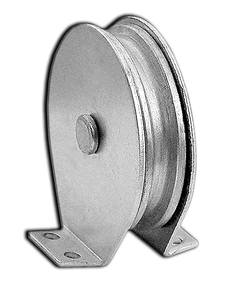 the globe to do so. These are the world-first functions by the progressive gearing and pulley devices (patented). Our fresh pulley theory overcomes limitations of brake and friction forces, which are the main factors behind wire slippage in typical pulley systems.
 units provide the most compact and rigid arrangement for large reduction of speed necessary for sluggish going machinery. A wide range of ratios up to 4900:1 is readily available.
 enough to eliminate. Tighten the tensioner pulley by turning the adjustment bolt clockwise with the ratchet and socket until the belt is tight.
 rest of the samples until their final break (this program can be modified based on the requirements).
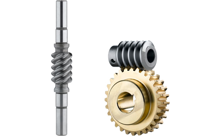 standard have diameters ranging from 20 to 135 mm and axial distances of 17 to 80 mm. Furthermore, we offer custom worm gear pieces with diameters as high as 300 mm and middle distances as high as 210 mm.
 actuators are really quiet. This is because of the very smooth operating of the worm gear combined with the utilization of cast iron and huge precision on component manufacturing and assembly. Regarding the our precision gearboxes, we have extra care of any sound which can be interpreted as a murmur from the apparatus. So the general noise level of our gearbox is reduced to a complete minimum.
 the 1960s. Belts are quieter and because of their material, less costly to produce. Timing chains are housed within the engine and receive lubrication from engine oil and can last a long time, while timing belts are located beyond the engine and tend to dry out and crack. In the last couple of years, however, more vehicle manufacturers have built-in timing chains back into some vehicles with huge improvements like a reduction in sound and vibrations, different then a timing belt not all water pumps are driven by the timing chain. Examine your owner’s manual to know what kind of timing
  because of corrosion and the occurrence of materials build in the roots of the sprockets. The chain is very suited, therefore, in handling components with a inclination to pack and corrode.
  become rotated or positioned during conveying. Belt conveyors keep the placement of conveyed items secure as they move, are less inclined to jostle or bump fragile items than other types of conveyors, and can support irregularly shaped products. Conveyor support stands, conveyor hardware, conveyor brushes, and conveyor guides are used to set up conveyors, support conveyors, and direct material movement on conveyors.
 design allows the links to move each other, reducing tangling and kinking. Used as an over-all utility chain about the farm and other industrial applications. The finish is specifically designed for outdoor applications.
 not display any gliding on or of the teeth, which posesses soft and practically noiseless gripping; this transmission was also designed for transmitting power or higher speeds than this was allowed for roll chains.
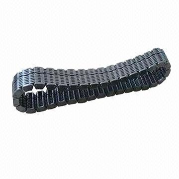 support. A web link belt silent chain contains
  Our light weight aluminum or metal timing pulleys stock allows you the flexibility to make pulleys in exact widths. Don’t start to see the timing belt pulley you need? Ever-power’s engineers will continue to work with you to produce the desired profile, just E mail us!
 quantity or quantities in leaf chains identifies the chain pitch, the last two numbers identify the chain’s lacing. New applications should use BL series leaf chains
 linkage and forks to slide a gear along the mainshaft, which is definitely mounted immediately above the cluster. After the gears are meshed, the clutch pedal can be released and the engine’s ability is sent to the drive tires. There can be a variety of gears on the mainshaft of different diameters and tooth counts, and the transmission shift linkage is designed so the driver must unmesh one equipment before to be able to mesh another. With these elderly transmissions, equipment clash is a issue because the gears are all rotating at distinct speeds.
 quote, please contact us and we will be happy to help you.
 it.
it. with the track links as effectively. This may accelerate the don of the sprocket and reduce the efficiency of your products.
 to any wheel upon which radial projections engage a chain moving over it. It is distinguished from a gear in that
  Chain are SUS304, SUS310, SUS316. They possess the features of high strength, high wear level of resistance and long life.
 on these components, adding to the service existence and reliability of the pump.
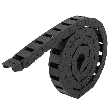 under extreme continuous loads and environmental influences. Our chains systems are quickly deliver-able at sensible prices.
 directions with a big sliding surface, which makes it a perfect chain for a very wide variety of applications. The look of the chain allows maximum flexibility therefore the chain can travel around obstacles and actually corners. This DF3498 chain is manufactured with high-quality metal and features hardened pins, bearing surfaces, and sliding surfaces to dramatically raise the strength and operation life of the chain. competitive cost directly from stock, in addition to a full type of high-quality DF3498 chain sprockets. There are
  worm gears, they are made to ensure that the tooth thickness of the worm alterations continuously in the axial path to ensure that by shifting the worm axially with shims, it turns into possible to change the backlash.
 , RC60 gearboxare
  a durable, double flex design for both horizontal turning and regular articulation.It retains its pulling power
  key or switch. This causes a clockwise or counter-clockwise rotational movement on the motor program, depending on the desired direction of movement. This prospective customers to a movement of the networked gears and chain to move in the same path as the motor. Consequently, the chain conveyor moves the strain through the drive train to the last gear, where off-loading is performed. For unidirectional functions, conveyor systems may also be tailor-made to provide movements to either path. This is accomplished through integrating several motors on either end of the conveyor system.
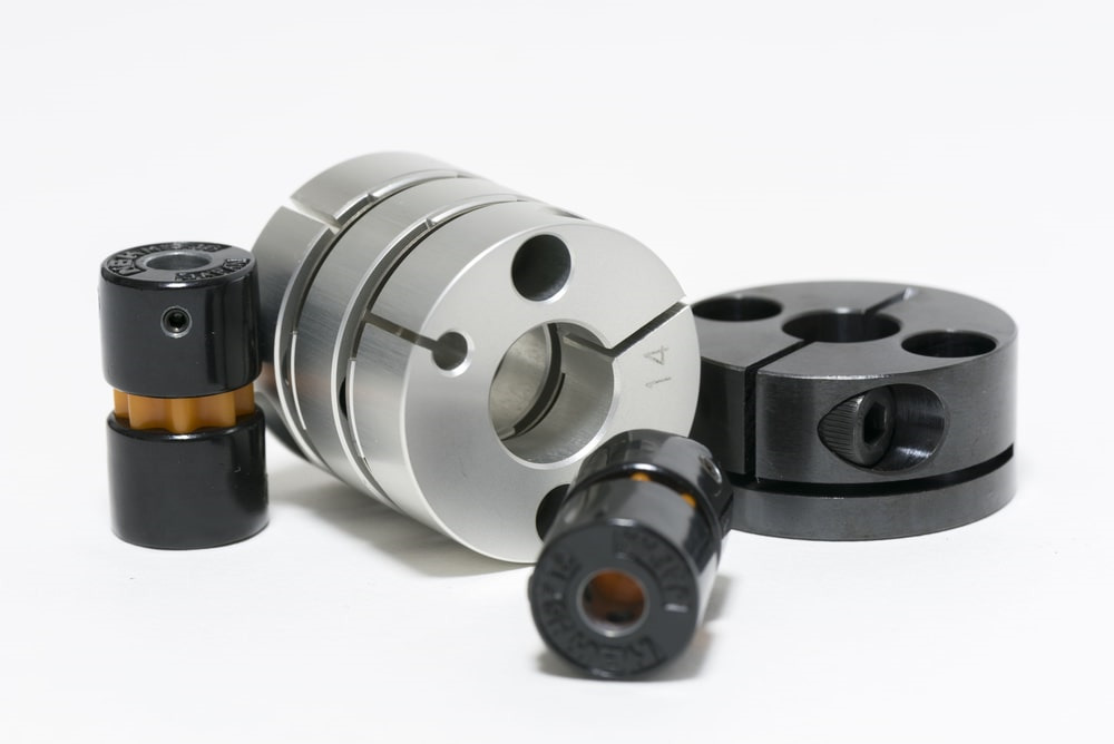 Flexible Shaft Couplings
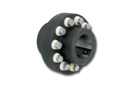 fitted.
 construction can withstand severe stress for extended periods of time, since does the track chain that drives them. Although these chains usually do not become butterflies like bugs of the same name throughout their life cycle, they are solid and strong and have been produced through years of fatigue-free operation. Our chains are forged to the American National Standards Institute (ANSI) requirements using the highest quality materials. Our manufacturers use quality recycleables to make sure that your manufacturing, agricultural or marine requirements are always met.
  place when the number of teeth on the small of the two meshing armor and weapon upgrades is less than a required minimal. To avoid interference we can possess undercutting, but this is not the ideal solution as undercutting triggers weakening of tooth in its base. In this situation Fixed gears are used. In corrected gears Cutter rack is shifted upwards or down.
 according to ČSN 02 3329. Our manufacturing program also includes non-standard bush chains produced according to our internal
  Co. Ltd
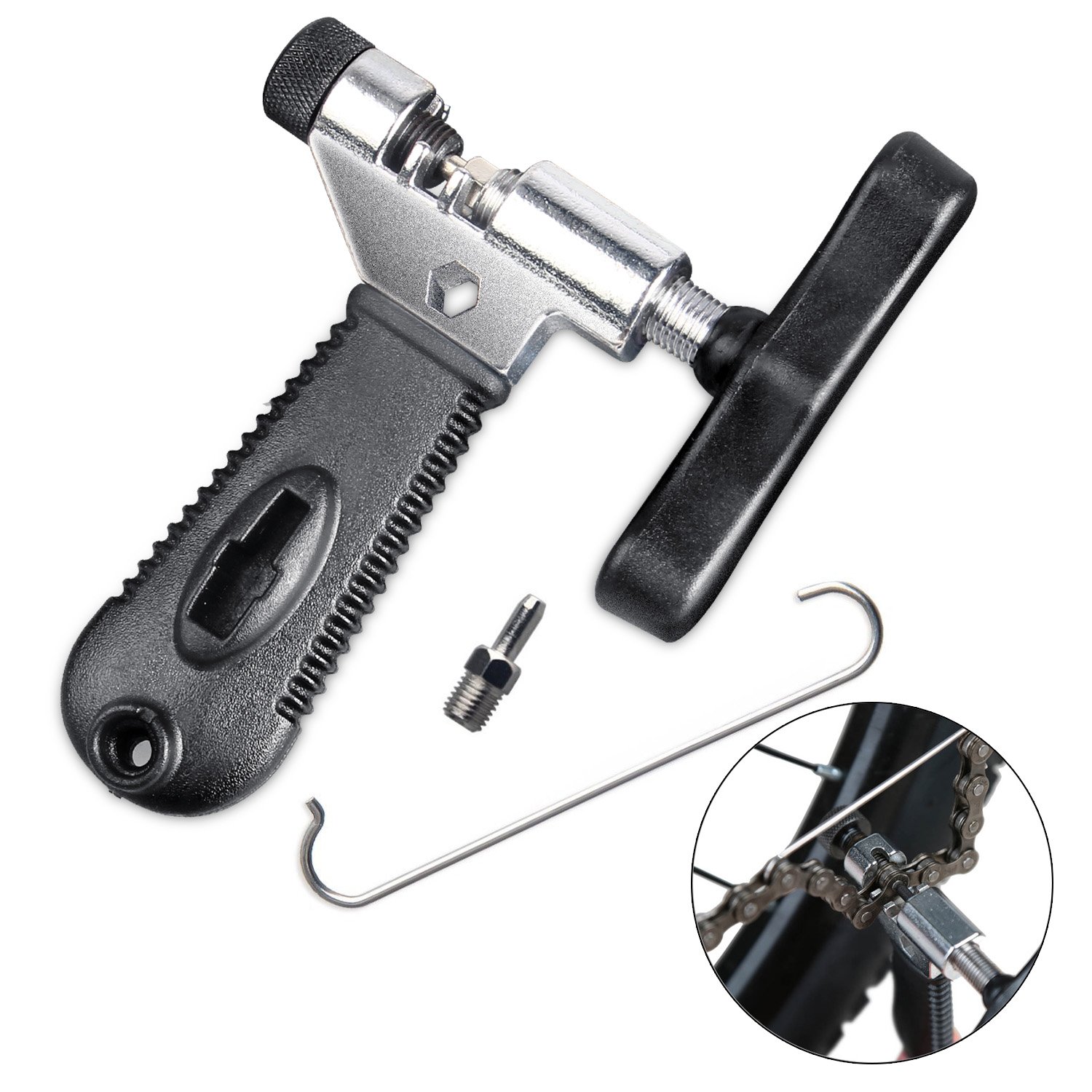 chain remover is in small design and portable to carry to anywhere anytime
 provide the next types of chains as :
 gear arrangement can be used for the 3rd category (nonparallel non-intersecting shafts). Unlike spur gears that have straight the teeth parallel to the gear axis, helical gears have tooth in helical type that are cut on the pitch cylinder. Although helical gears are commonly used for parallel shafts like spur gears, it can also be utilized for perpendicular but non-intersecting shafts.
 bearing loads.
  the different tooth shape, it is not possible to cut many gears simultaneously by stacking the gear blanks as can be carried out with spur gears.
 Pitches (DP and Module)
 spiral bevel gear drives have double-shielded, permanently greased, standard-metric-series ball bearings. The gears are constructed with hardened alloy steel and are contained in an aluminum alloy housing for maximum strength and heat dissipation. They are lubricated for life with. Bonded seals keep lubricant contained in order to avoid product contamination and decrease unnecessary maintenance or cleaning. equipment drives may also be customized to match applications that require certain materials. They have multiple flange and body-mounting surfaces. Unique materials can be included in shaft extensions and various other modifications, which can be made to suit any unit.
 quickness of translation is a multi begin thread may be used. This implies that multiple thread forms are manufactured on the screw shaft.
 trim and types.
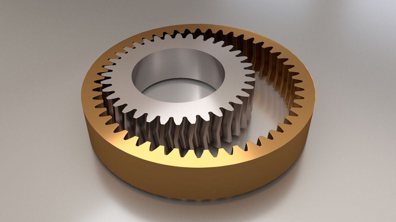 and chemical applications. We also serve customers in the medical, auto, biotechnology, and packaging industries. Our internal gears could be stated in diameters up to 42″, with a maximum diametrical pitch of 2.5, and a optimum module of 10.
 supply you with reliable quality workmanship – metric gears of the best quality.
 the tires is turned, the contrary wheel will turn in the opposite direction at the same acceleration.
 as being versatile, gear couplings are extremely much considered to be a versatile coupling. A gear
  Ideal for positioning elements such as bearings or sprockets onto shafts.
 the primary gearbox circumstance and the enter/output caps. Try including or removing some of these spacers until finally your gears have roughly one/eight”-1/4″ of free engage in. Specialists can buy replacements ($one-two) in various thicknesses, but we recommend the fast and filthy technique of cutting your very own out of a sheet of mylar.
 be lubricated and with a higher impact plastic material wheel and galvanized chain/housing won’t rust or corrode.The innovative swiveling chain guide allows for tension free chain pulls from directly below the gear or at an angle. The travel ends are 0.75 inch and also have holes drilled through them to secure the drive or roll-up tubes attached to ends.
 non-intersecting shaft at correct angles. Worm gears and worms, which resemble spur gears and screws, respectively, combine to provide a high
  clamping collars must be set up by sliding the collar over the end of the shaft, while two-piece clamping collars separate into two halves and may be installed between elements on the shaft. Shaft collars are made from a wide variety of materials including zinc-plated steel, light weight aluminum, nylon, and neoprene. Found in nearly all sorts of machinery and sector, shaft collars are used in applications which includes gearbox assemblies, motor bases, machine tools, drive shafts, agricultural implements, medical equipment, and paper and steel mill equipment, amongst others.
 Options: Custom made Center
  to 300 mm, axial distances from 17 to 210 mm, module from 0.5 to 10, shaft size up to 500 mm
 are able to produce tooth and size ratios as high as 1.5 DP and 16 modules. With instant creation and scheduling features, we can work with our customers to determine the most efficient and useful way to manufacture and transfer worm gears and worm models.
 sent to each wheel. Worm gears are accustomed to provide the required torque that governs each wheel’s performance.
 Plastic Chain Coupling
 group.com/Coupling/picture/fluid%20coupling3.jpg]#yoxvs versatile bucket wheel excavator fluid coupler, welcome to wholesale the greatest high quality, protected and tough products with our manufacturing facility. We also welcome tailored orders. Check out the value checklist and the quotation with our makers and suppliers now.
 free
free  in the vacuum pump by using a liquid seal. … When the impeller begins to rotate, the liquid is usually starts move outward by centrifugal drive.
 and the pumps can reach a pressure of 1 1 x 10⁻⁴ Torr. Rotary piston pumps could be ready for corrosive and oxygen provider.
 widely used in vacuum smelting, vacuum welding, vacuum casting, vacuum coating, vacuum drying, vacuum dynamic experiment and chemical substance pharmaceutical, electric vacuum gadget manufacturing industries.
 costs. The pumps can be found in capacities of maximum 6 m3/hr plus they are able to reach vacuum pressure of 10 mbar(a). Used as a compressor they reach a pressure of approx. 7 bar(g) maximum.
 without disassembling pump
 screw
screw  should.
 Coupling/picture/fluid%20coupling2.jpg]#dimension 7., 9.four and 12.four
 requirements of oil-totally free large pumping quickness clean vacuum environment proposed by these industries because of the restrictions of pumping speed characteristics and structural mechanism.
 drug on the traditional globoid gear. An experienced in the art engineer would instantly derive possible design advantages of the wormoid equipment. For example, using of the wormoid gear can significantly reduce cost of electric powered assist mechanisms that are generally applied to modern automobiles. Due to the bigger driving efficiency, wormoid equipment set can be made with increase ration and provide the same driving efficiency as the original worm or double enveloping worm equipment. For instance NSK worm equipment steering actuator with a ration of about 20:1 delivers about 80% of driving efficiency. The plastic gear would hold about 80 Hm of torque. An alternative wormoid gear design from Ever-power would be capable to increase the ratio up to 30:1 and the torque on the apparatus up to 150 Hm without increase of the guts distance between the equipment and the pinion.
 only has a vacuum level adjustment. A VSD for a vacuum pump is usually economical for a dairy that milks a total of 8 hours or more each day. Typically a VSD will never be a cost-effective option for little dairies due to less milking time and thus shorter vacuum pump operate times but there are several other choices to save lots of energy costs.
 the lubricating and cooling process. These alternate materials guard the pump and invite the mechanism to go smoothly with no need for any oil-structured or synthetic lubrication.
 it’s time to recharge. Before recharging you really want to make sure the
  the procedures. By integrating condition monitoring, information about the condition of the vacuum system is always available. In addition, condition monitoring increases program availability, allowing users to program maintenance and repair actions in a useful and anticipatory way and prevents cost-intensive creation downtimes. These advantages lead to a long service life and maximum operational protection. ever-power vacuum pumps can either become aligned vertically or horizontally. This allows maximum pumping speed and a far more customized and efficient usage of space at the customer’s production site.
 the ER-Series of Two Stage Piston Air Compressors can work for you.
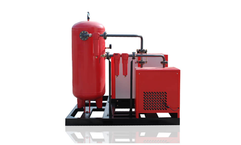 oil-air compressors, the oil-drinking water separator function: separates the essential oil from the moisture in the atmosphere and for that reason accumulates over an extended period of period and can affect the filtration effectiveness without the need to replace or clean the oil-water separator
 of rewards. In addition to straightforward assembly and disassembly, a clamping box is normally cost-efficient when compared with other answers. Typically, wit
 h a worn sprocket, the clamp can be reused.
  of a essential
 HP continuous duty motor, All steel pressure hard lines and hydraulic design flex lines
 compressors. This also allows screw compressors to end up being significantly quieter and produce much less vibration than piston compressors.
 a bevel gear is and how it operates, so as to comprehend its utilizes and learn how to decide on the most suitable for our task.
 The shafts’ bearings
  ZZ009545 22.68 L/Min 220
 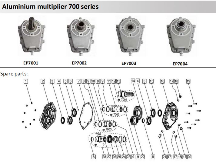 556 33.86 L/Min 150 Bar
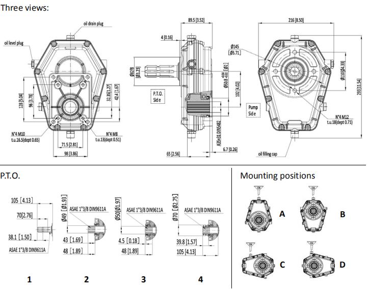 ctrical power get offs is 540 rpm which can be in distinction with the ideal managing speeds of hydraulic pumps.
 the slewing band to rotate; The outer ring result the torque through the flange and the inner band of the slewing band is set in the housing.
 a producer of Chinese worm gear shafts. Our intensive experience, productivity and features provide us a competitive price in the worm and worm shaft markets. Our knowledge in a variety of machining processes we can create worm gears and worm shafts with different designs, sizes, capacities and specs.
 pre-stage gears (already present in the catalogue of CHM) can also be mounted with this range, obtaining a gear ratio up to 1 1:300. For bigger reductions is possible to possess two gears together using an appropriate kit
 easy to operate and is used in a number of applications across
  offset, causing eccentricity. … The actions of the vane drives out the same level of fluid with each rotation. Multistage rotary-vane vacuum pumps can attain pressures as low as 10 mbar (0.0001 Pa).
 … Timing gears with essential oil reservoirs and close clearances between your rotors and housing are additional attributes that make up a dry vacuum pump.
 operation.
  screw chambers and transports it to the gas discharge. The advanced screw style results in lower electrical energy consumption compared to standard screw designs. In addition, it results in a lower temperature load of the compressed gas.
 is a leading producer of precision gears for all applications. We provide precision gears in standard and custom made inch-measure sizes and a number of configurations, including spur gears, anti-backlash gears, worm gears, helical gears, bevel gears, miter gears, pinion gears, and more.
 performed by the operator and without the need for special tools.
 start-up kit, and receive all of the parts you need for start-up and the 1st season of maintenance, along with a protracted pump warranty
 Gearmotors line allows our customers to have a suitable product for each application, where small size and good performance are the objective to meet.
 uses a mixture of the reciprocating
  worm wheel round, it is never the contrary way circular as the system tends to lock and jam
 their specific specifications. Whether you need high or low volume, large or small size worm gears, we can accommodate a multitude of requirements. E mail us with questions or to get a quote.
 to the long services intervals having less abrasion also eliminates most of the particulate impurities regularly generated within scroll or piston pumps. This makes diaphragm pumps a good choice for clean applications.
 totally oil free and do not have any sliding parts in the gas route. In normal procedure they are completely free of abrasion. Besides contributing to the long support intervals the lack of abrasion also eliminates most of the particulate impurities regularly generated within scroll or piston pumps. This makes diaphragm pumps a good choice for clean applications.
 additional solvent which is certainly rotated by an impeller within the casing of the pump.
 bronze with a 303 stainless steel hub.
 between these types of pumps and centrifugal can be that positive displacement pumps will move liquid at the same speed regardless of the pressure on the inlet end and centrifugal pumps will not
 do not pollute the transmission medium.
 of gearing.
 increases its velocity and lowers its air pressure. Ambient air is used through channels in the generator, creating suction and vacuum. The surroundings stream exits through the exhaust. … These functions require vacuum pumps.
 ability to prohibit back driving
 maintains vacuum in a closed space simply by various means.
 to compress the air flow out of the chamber.
 air compression efficiency.
 available .Creation and profitability depend on encounter conveyor hours; ifs period to take benefit of HZPT’s strength.
 mini-excavators, and 3-position hitch tractors. Hydraulic Auger Methods offer reverse
  when an auger is trapped and the motor will stall removing shear bolts in difficult digging problems.
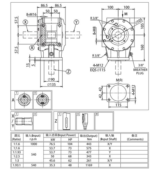 AGRICULTURAL Equipment
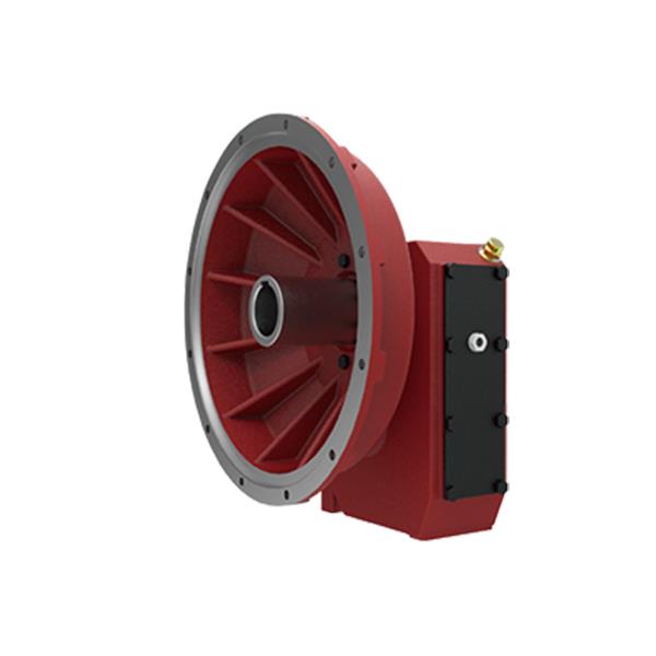 particular-way clutch
 ox.xyz/uploads/201817269/agricultural-gearbox-for-generator15513606228.jpg]#and correct angle shaft velocity increasers and reducers), driveshafts and safety devices mainly employed on agricultural equipments.
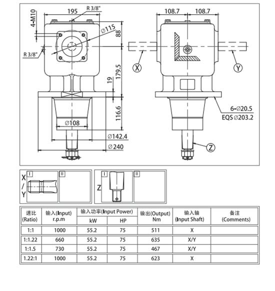 Skilled QC area and inspection equipment to handle dimension and backlash and noise nicely.
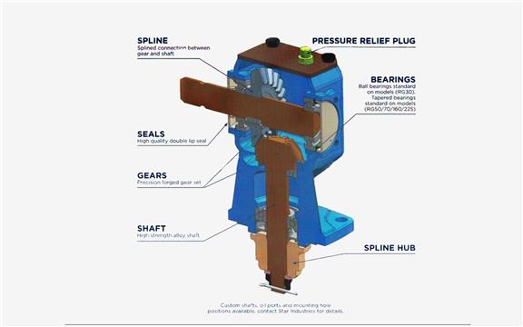 90° Appropriate Angle Gearbox is chosen by all racers in the FXT(Outlaw Twin) and FXS(Outlaw solitary) Courses when heading from a vertical shaft motor to the horizontal rear axle. This is a significantly more powerful set-up and demands considerably less maintenance than a 700 sequence or equivalent multi-equipment transmission. By decreasing the variety of moving parts and trying to keep issues easy this gearbox is the go to for any create exactly where guidelines let.
 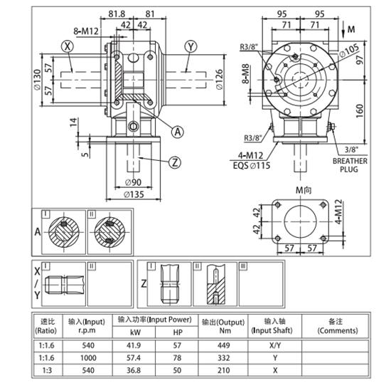 correct rotation, ratio 1-one.6 revs from pto shaft to key shaft mounting sample 120 by 100mm or 153 mm diagonal with 16mm bolts important shaft 34mm plus key with mounting 12mm bolts 85mm aside or one hundred fifteen diagonal FAQï¼ 1.WHAT Programs DO YOUR Items RELATE…
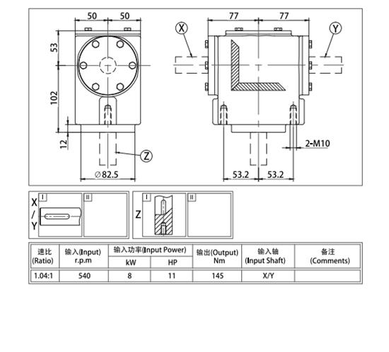 dimension and input pace and gear ratio are offeredï¼EPG could provide youwhatever you want.
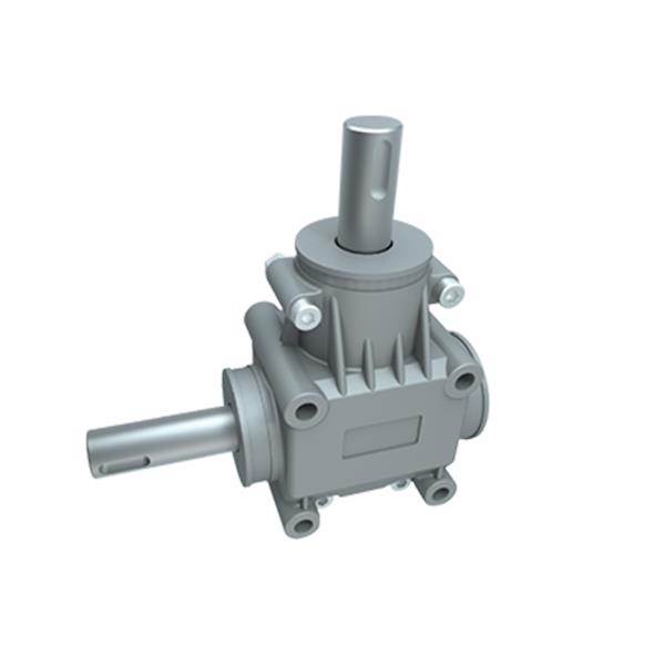 Coloration.Consumer Requests
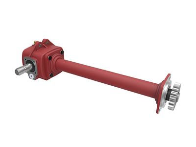 Kit
Kit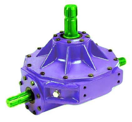 sort of as replacement hoppers or manage levers are needed, depend on ever-poweri Source ® for good quality and selection. Our fertilizer hopper and spreader areas are amongst the many farm machinery elements we carry. We provide spreader gearboxes as well as stainless metal spreader discs with vanes. Select At any time-energy ® substitution spreader elements fret-cost-free, because consumer provider arrives 1st at EP Supply.
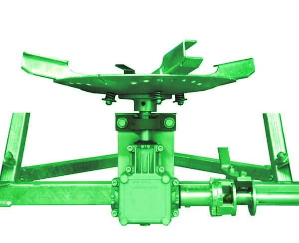 spreaders is developed to be towed driving a yard tractor, ATV, or like vehicle.. These are quite comparable to the spreaders that mount to the three level hitch of a tractor, but are best for landscape and tiny property maintenance, and for the individual that will not have a tractor with a 3 point hitch and PTO. We market the two varieties, right here at EP Attachments.
 large overall performance for the whole section of this market.
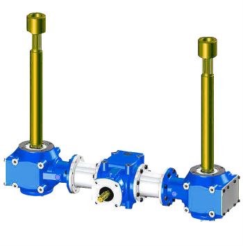 y mower parts, you have come to the correct spot. EPG Provide has a vast selection of the top brand names to fit your certain mower and any tough process you require to deal with. Browse our choice to find out your a lot of alternatives in these important parts to keep life on the farm operating smoothly.